Shortly after the end of World War II, Prof. Joseph E. Henderson proposed a 60-inch cyclotron for nuclear physics research at the University of Washington. Construction began in April, 1948, and full external beam was achieved in 1952 under the leadership of Prof. Fred Schmidt (see Rev. Sci. Instrum. 25, 499 [1952]). An account of those early days was written by Harold “Bud” Fauska, Physicist and Senior Research Engineer. The Cyclotron’s application shifted from basic research to neutron therapy for cancer patients, and it operated until 1986.
In the early 1960s, NSF granted funds for two cascaded High Voltage Engineering Model FN Tandem Van de Graaff accelerators and a new laboratory building, the Nuclear Physics Laboratory (NPL). In 1985 a superconducting linear accelerator was completed. It was injected by the second electrostatic machine, and the first one was decommissioned. High-energy heavy-ion beams could then be obtained for nuclear physics research. The “Linac” operated successfully until 2000 and was then decommissioned. The single Tandem remained available for fundamental symmetries and low-energy nuclear physics research. A short history of this period has been written by Prof. Derek Storm, who directed the Linac project and the Nuclear Physics Laboratory until 2008.
In 1994 a shift away from accelerator-based research began with the Sudbury Neutrino Observatory project, and in 1998 the Nuclear Physics Laboratory formally became the Center for Experimental Nuclear Physics and Astrophysics (CENPA). The Center carries out experiments in gravitation, neutrino physics, fundamental symmetries, and dark matter.
University of Washington cyclotron
Harold Fauska, Physicist
September 2010
History
The activity of owning a cyclotron dates back in the late 1930’s. Stranahan mentions it in his book on modern physics about 1937.
When I first started work at the cyclotron laboratory in 1951, I was privileged to see the original magnet yoke and the dee cavity before it was disposed of.
The materials were provided by the University and the Swedish Hospital. Professor Joseph Henderson was the main researcher. Research was not accomplished because of high vacuum problems. The active dee section was about 10 inches in diameter.
Professor Henderson was doing research with the US Navy and it was through that contact that the University constructed the final cyclotron and the original laboratory buildings. To the best of my memory the starting time was 1948.
The location placed the cyclotron in the hillside with a 4-foot deep water pool directly above the cyclotron to provide shielding from radiation entering the areas nearby.
Two cooling towers were in the now parking lot. One water cooled the insulating oil pumped through the magnet coils, typically 400 amperes at 400 volts. The second tower cooled the dee stems and the dees, typically 150,000 watts.
Professor Henderson was the main man in charge of operations. The University hired Ted Morgan. Ted was a physics grad student at the Crocker Lab [the UW cyclotron was modeled on the one there], with E.O. Lawrence, the inventor of the cyclotron. Most technical decisions were the responsibility of Ted. The mechanical engineer was Ned Brandt. The electrical engineer was Harold Engerbretson. The First machinist was Harvey Bennit. The Second machinist was Albert Willman. The electrical work was done by John Orth and Robert Elliot.
Early Operation
The first students were doing magnetic field measurements. Field measurements were very painstaking and many.
A flip coil was positioned at a location and the flux change voltage then measured by a flux meter, which was a charge meter called a ballistic Galvanometer. The charge collected by the coil flipping 180 degrees in the given area of the 60-inch pole face must be equal over all the total area.
Measuring the radio frequency potential was another project students and staff were checking from time to time. Typical dee voltages were 100,000 volts.
Control of the cooling waters required many flow switches. The relays forming a network of interlocks filled several relay racks and used many miles of wire. The blueprint of the interconnections was about 30 feet long and 3 feet high. The print filled the wall space behind the relay racks.
The magnetic field was near the saturation of iron, about 15,000 Gauss. Using that field required the power oscillator frequency to be around 11.47 megahertz to yield the so-called cyclotron equation to provide acceleration at the dee crossing.
The dees were at the end of stems one-fourth wavelength at 11.47 megahertz. Dee-to-dee spacing was about 5 inches and the outer ends were tapered to give an increasing spacing to allow for the greater speed as the energy increased.
The ion source was contained in a carbon chimney-like tube located in the center of the dees. Inside the container was a hot filament and a top disc of carbon.
The voltage from filament to disc was 400 volts. Electrons were emitted from the filament and since the magnetic field was vertical along the container, the current flow was always vertical. The selected gas was injected into the container and the electrons’ flow would strip the electrons from the gas leaving positive ions to be extracted out of a small slot in the container. When the dee voltage was negative, the ions were extracted and now being charged they would start in a circle and accelerate across the dee-to-dee gap.
If the magnetic field and the oscillator frequency were correct, the ion would move in a half circle and now be accelerated across the opposite dee-to-dee gap. Under proper settings the ion would make about 90 such ever-increasing circles.
The condition described allows a probe to be placed along the dee-to-dee space and, using an appropriate target material, bombard it at the energy of the circle the ion strikes.
Tuning was done with a fixed frequency and varying the magnetic field. The cyclotron was at this level of operation when I was hired.
Experimenters were doing experiments using electronics located at the cyclotron housing. The rf radiation was so strong at that frequency filtering and shielding was restricting any real, accurate data.
Professors like George Farwell and Fred Schmidt were now involved in doing research. George had been at Los Alamos working with Enrico Fermi. Fred had been at Oak Ridge working with Calutrons.
Calutrons are the magnetic separators used to separate U-238 and U-235. Fred had set up a beta spectrometer at Physics Hall [on UW campus] and was extending the research to the cyclotron.
Experimenters were trying for more energy. The current was maximum with the internal probe at 19 inches. The circulating ions become dispersed beyond the 19-inch radius.
There was much discussion at the meetings. Professor Henderson had different thoughts about a possible solution than both Fred and George.
The issue of classical physics and quantum physics seemed ever present at this time. Professor Henderson was now active with applied physics and the continuing Navy funding. The cyclotron was now funded by federal funds.
The final action: Professor Henderson left the cyclotron and directed Applied Physics. Fred did a review of the magnetic profile and they installed an extra ring of iron around the outer 7 inches of the magnet top above the dee housing.
After much testing and ring size [adjustment], the ion beam would stay intact out to the design distance of 30 inches.
The next project was to extract the ion beam. The end was to install an open section of the west dee and replace it with a graphite very thin section having a V type opening. A DC powered water cooled deflector following the contour of the dee [biased with] typically 20,000 volts would pull the ion beam away from the internal path to circle the dee ending in a target chamber housing a faraday cup after going through any given target material.
About this time the faculty was approached by diamond merchants with yellow diamonds. Their interest was in exposing the diamonds to nuclear radiation, mainly neutrons. They would become blue green diamonds. The initial test proved the concept was correct. The faculty decided not to get involved. The decision was made in spite of the pressure of merchants. The laboratory had just obtained national funding and such activity would not be an asset to their research credibility.
Data collection was beset with interference of the intense RF background and the nuclear radiation from within the cyclotron. Signal-to-noise ratio was a constant battle. The need to channel the extracted beam through the provided water-shielding chamber was a necessity.
On the completion of the shielding provided by the water and thick walls, data signal-to-noise ratio was at a useful level.
An analyzing magnet was added to provide a more precise energy resolution.
A scattering chamber using high-resolution angle of target to detector increased the type of data the experimenter could perform.
E.O. Lawrence's brother was doing medical research on cancer. Space travel was on the horizon and the researchers were interested in radiation damage to the living tissue. The research time was divided between pure physics and the radiation effects.
The Lab-provided irradiation of visiting prospective space candidate’s gravity loss and calcium loss were some prime issues.
The interest accelerated in the calcium loss. The targets were pork roasts, cadavers, chimpanzees. After much research, live people were bombarded. The subject was first surrounded with water and rotated. The water was later replaced by thick plywood walls and still rotated during the radiation. The water and the plywood assured a more uniform irradiation of the patient.
The radiation resulted in making calcium in an isotope that was radiating. The half-life is short so the patient was rapidly run through a whole body counter.
The total calcium in the patient could be measured. The data and all patient handling was performed by medical personnel from the university medical facility. The testing was so popular the Lab tested patients from as far away as the central states.
Research advanced to providing the positron emitter isotopes used in positron emission tomology. Medical staff was always involved in any use of the cyclotron-produced medical items.
The physics research for physics students was always provided. Several doctorial and master’s degrees were granted during the time period discussed.
The scattering chamber provided angular studies. Numerous energy amplitude spectrum research [studies] were carried out. The Lab also helped many foreign students do the data collection to support their graduate work.
The early students were active in the machine development. Their later life was a continuation of that type of work on many related machines.
The medical research ended with the University medical school purchasing their own cyclotron. Much of the technical operation was by people with experience gained working at the original cyclotron Lab.
The cyclotron last ran in 1986.
History of the Van de Graaff and Superconducting Linac
Derek Storm
March 2019
Van de Graaff Accelerator at the UW Nuclear Physics Lab.
In 1962-63 the NSF provided funds for the purchase of a Van de Graaff accelerator along with associated equipment and the new building. The accelerator was to be purchased from High Voltage Engineering Corporation in Burlington MA. The accelerator was a “three-stage” system consisting of a model FN tandem accelerator and, in a separate tank of the same dimensions, an injector. The tandem accelerator accelerated negative ions to the positive terminal where they were stripped in a gas stripper and then accelerated again as positive ions. (Hence the name “tandem” as opposed to older electrostatic accelerators which had an ion source in the terminal.) It could run on its own with a negative ion source, or it could be injected with negative ions from the injector Van de Graaff. The injector Van de Graaff took “neutral ions” (initially positive ions, focused toward the terminal outside the tank and then neutralized) and added an electron at the negative terminal. Both accelerators used a rubber belt for charging the terminal, and the beam tubes were the HVEC inclined-field tubes, made of glass and aluminum. The gradient was established with resistors connecting each plane of the beam tube. Fine energy regulation was accomplished with a corona discharge from the terminal which was controlled with a vacuum tube. The insulating gas was a mixture of N2 and CO2 at around 15 bar.
The negative ion source provided with the tandem was a duoplasmatron, which made a beam of positive ions which then passed through a canal with an “exchange gas” where some of the positive ions picked up electrons and the negative ions were injected into the accelerator. Over the years a variety of different ion sources were built and used.
The accelerator system included a 90-degree analyzing magnet with “image slits” providing feedback control of the tandem terminal voltage. Following the image slits was a switching magnet with 7 ports, which could put the beam into beam lines in two experimental areas. Four beamlines were included.
An improved version of the 60” scattering chamber used with the existing cyclotron was built and installed on one of the beamlines.
The building was completed and occupied during the academic year 1963-64, but because of delays at the factory, the tandem was not delivered until summer of 1964. The Laboratory’s 1965 Progress Report states that the tandem was installed but "Work is in progress to develop a beam of usable intensity and stability.” There were many problems with manufacture that should have been detected at the factory. Nevertheless, people in the laboratory were already developing a buncher/chopper to do time-of-flight measurements. The first research data was obtained on May 13, 1965.
By the 1965-1966 academic year a broad and active research program was going on with the tandem, using beams of protons, deuterons, 3He, 4He and 16O. This research was led by Professors John Blair, David Bodansky, John Cramer, I Halpern, Fred Schmidt, and Robert Vandenbosch. In addition there were a number of Postdoctoral Fellows who often led their own research projects, independent of the senior faculty. Having beams with a wide range of energy variation but also a precise setting and good resolution (several keV) was a new experience for a laboratory used to the fixed energy and 100-200 keV energy resolution of the cyclotron. Experiments involving excitation functions (study of analogue states in heavy nuclei and a detailed balance test of time reversal invariance, for example) were initiated. About a dozen different experiments using the tandem were listed in the 1966 Progress report. The SDS 930 computer was delivered and installed for online data taking.
The injector Van de Graaff was delivered and installed in the academic year 1966-1967 and the beam bunching system was completed and installed. After six months of testing and vacuum leak chasing, it passed the acceptance tests, with the “three-stage” operation producing a 23.6 MeV proton beam of 0.6 µA. The injector was able to reach 7 MV. A second scattering chamber (24” chamber) was built and installed. One of the first experiments to use the three-stage accelerator was a measurement of proton spin-flip at 20 MeV.
During academic year 1967-1968, substantial improvements were made in the negative ion source to improve the intensity of He beams. At this time a continuing effort began to understand the voltage fluctuations in the tandem terminal and to control them. It was noted that the belt had structure that affected the charging, and so there was a ripple around 30 Hz on the terminal that corresponded to the belt geometry. The corona regulator had a relatively slow response (90 deg phase shift around 10 Hz) so it could not eliminate this ripple. The ripple could at best be limited to about 0.5 kV peak and was noted as the limiting factor for energy resolution. This continued to be a limitation of the machine for a number of years.
That same year, a foil stripper was added to the tandem. The transmission of a proton beam was increased from 20 to 80% with this stripper, and the foil stripper would provide higher charge states of heavy ions than the original gas stripper. A “direct extraction” ion source was designed, built and installed during the academic years 1968-70. By extracting negative ions directly from the duoplasmatron, higher intensity and lower emittance beams could be obtained than were available from the charge exchange ion source. But the primary motivation was the fact that the energy spread was smaller, enabling the beam buncher to operate effectively. Beam bunches of 1.8 (FWHM) ns were obtained – a factor of 3 improvement over the bunches obtained with the exchange source.
An ion source for Li ions was built. (The negative Li ions were produced by collisions with a positive proton beam in a gas exchange canal containing Li vapor.) Plans for a polarized proton ion source were developed, and construction and bench testing were taking place during academic year 1969-70.
During the 1970’s there was emphasis on reducing the terminal ripple (using a power supply in the terminal fed back on the energy slits, with an LED and photo-transistor to transmit the error signal to the terminal). A sputter ion source was installed that provided many different heavy ion beams, and the fraction of time devoted to heavy ion beams increased. By the end of the decade, light, unpolarized ions and heavy ions were used about the same amount of time. The polarized ion source was installed and typically used about 20% of the time. A terminal ion source was installed in the injector. Injector use diminished from about 30% of the beam time in 1971 to about 5% in 1978 and 1979. In 1974 a paper1 was published describing the machine.
In the early 1980’s the injector use increased to about 10% of the time. Eventually the injector was removed in order to provide space for components of the linac. The injector Van de Graaff was sent to Livermore, where it was dedicated to accelerator mass spectrometry operation. Throughout the ‘80s, there were various efforts to understand the behavior of the belts and to minimize the terminal ripple.
Finally the ripple problems were solved by replacing the belt with a Pelletron charging system in 1993. A Pelletron is a chain with alternating insulating and conducting links. The conducting links are charged by induction, and since they are identical, each gets the same charge, resulting in a uniform current delivered to the terminal. As part of the same upgrade, titanium spiral inclined-field beam tubes were installed, replacing the original style aluminum inclined field tubes. (The field in the tubes is “inclined” meaning there is an alternating transverse component to sweep away electrons emitted from the tube electrodes.)
Also in 1993, installation of a terminal ion source for the tandem was begun to be investigated. This source would provide high intensity beams of He, but at lower energies than could be provided with an external negative source. For many experiments in nuclear astrophysics or studies of fundamental interactions, low energy beams with high intensity were desired. A source was obtained from NEC and installed during academic 1993-1994.
These various developments on a 20 year old accelerator indicate the versatility of the machine, which is still being used in 2019.
Superconducting Booster Linac
During the academic year 1981-1982, a proposal was initiated for a superconducting linac to be injected by the tandem. Funding was finally granted in 1984, and the design settled on a system using two different size quarter-wave resonators. These were lead-plated copper, cooled with 4.5K liquid helium. The accelerator would have 24 “low-beta” resonators optimized for particles with speed 0.10 c followed by 12 “high-beta” resonators optimized for particles of 0.21 c. These would go in a total of 12 cryostats. Either 4 low-beta or 2 high-beta resonators would go in a single cryostat. In addition, there would be two buncher resonators, a low-beta one ahead of the linac and a “rebuncher” after the accelerator using a high-beta resonator. These each had its own smaller cryostat. In order to fit into the existing building, there was a 180-degree bend between the low-beta and high-beta halves of the accelerator.
The resonators would operate at 150 MHz. The quarter wave resonators have only two gaps, so the range of velocity particles they can effectively accelerate is quite large. The lead plated resonators were expected to achieve average accelerating fields of 3 MV/m, and the system was expected to yield 36-MeV protons and light ions of energy 20 MeV/A, decreasing to about 10 MeV/A for mass 40.
In order for a linac to be injected by the tandem, the beam had to be bunched into bunches much shorter than the 6.7 nS period of the linac rf. A buncher operating at 50 MHz, using three harmonics to produce a relatively linear ramp was built. The beam from the ion sources was only around 30 keV, and in order to get good quality bunches, a higher energy beam was needed (because the energy spread imposed by the buncher is a fraction of the beam energy, and the energy spread imposed by the buncher must dominate the overall energy spread of the beam, including that resulting from straggling in the stripper, to get a narrow bunch). So the injector Van de Graaff was replaced with an injector deck operating at -300 kV. This had the additional advantage of providing a smaller emittance beam into the Tandem, helping with transmission.
By the summer of 1987 the linac was running and able to deliver a 170-MeV 16O beam for an experiment. By the academic year 1988-’89 we had achieved 225 MeV for 16O and 340 MeV for 58Ni. These are 14 MeV/nucleon for O and 5.6 MeV/nucleon for Ni, which is at the high end of the mass range for the accelerator. A summary paper2 was published in 1990. Average accelerating fields of 2.8 MV/m could be obtained for extended periods with the low-beta resonators, and 2.4 MV/m could be obtained for the high-beta ones. By academic year ’91-92, the low-beta resonator field was improved to 2.9 MV/m, but the high-beta field remained at 2.4 MV/m. Regular operation provided beams of protons, He, O, 32S, and masses up to 58Ni. By 1999 the low beta resonators could be operated at 3.0 MV/m on a regular basis. But interest in the beams provided by the booster was waning and only a 40Ca beam was produced in the period March 1, 1999 to Feb 28, 2000, and the machine was only used for 28 days during that year.
Unlike the tandem, which can be turned off and ignored for an extended period, and then turned on and be ready for use in a day or two, the booster linac required continuous attention whether it was running or not. The cryogenic system, which circulated and re-liquified the He to maintain the system at 4.5 K required continuous attention, whether the rf of the linac was on or off. Thus it was impractical to maintain the linac for limited experimental interest, and the machine was “mothballed” during 2000. It was eventually disassembled and much of the equipment surplused or scrapped.
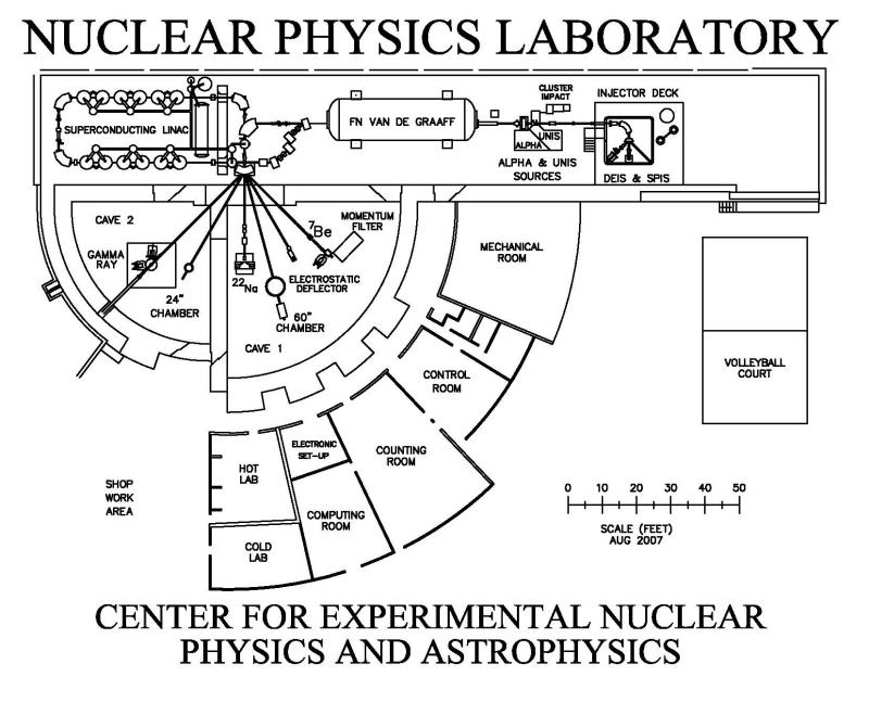
This drawing shows the tandem and linac along with some experiments that were running in 2007. Not shown are the helium compressors for the linac cooling. They were in the space to the right (East) of the injector deck. Before the linac was installed, the injector Van de Graaff was located in the region later occupied by the injector deck.
Bibliography
1.) “The University of Washington Three Stage Van de Graaff Accelerator,” W.G. Weitkamp and F.H. Schmidt, Nucl. Instrum. Meth. 122, 65 (1974).
2.) “Status of and Operating Experience with the University of Washington Superconducting Booster Linac,” D.W. Storm et al., Nucl. Instrum. Meth A 287, 247 (1990).